August 2, 2025
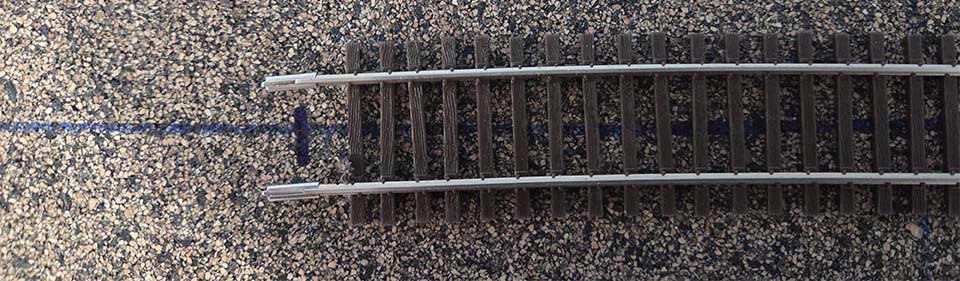
Before laying the staging tracks, the tangent to the curves had to be determined. Since the straight track is parallel to the wall, running a square along until the shortest distance is found locates it.
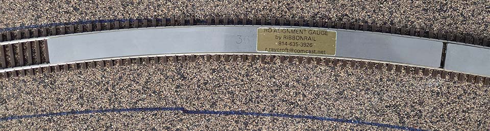
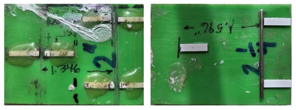
Two lengths of Micro Engineering code 70 rail were soldered together. After manually adjusting the curve, Ribbon Rail Alignment Gauges were used to smooth it out. The second curve from the edge of the layout had a 40″ radius and I had a pair of them. After using them, the curve still did not match the radius line. My current minimum radius is 36″ so I tried those. Perfect alignment! I might add that all curves on the layout were drawn first, and track made to align. The CAD drawings included easements. The staging tracks do not have easements going from 33 3/4″ to 57″. 2 1/4″ spacing was used for the first four smaller radius tracks and 2″ for the remainder.
Fifteen years ago, I made a simple track spacing gauge. Now commercial ones are available for around $35. A 2 1/4″ one was needed, so the old one was flipped and a new one constructed. HO scale 2 x whatever gives the right distance to clear spikes. ACC held them in place and then epoxy was applied so they don’t pop off.
Before fastening the track down, a Dremel disk was used on the bottom of each rail to make it easy to slide track joiners on. This was done throughout the layout construction.
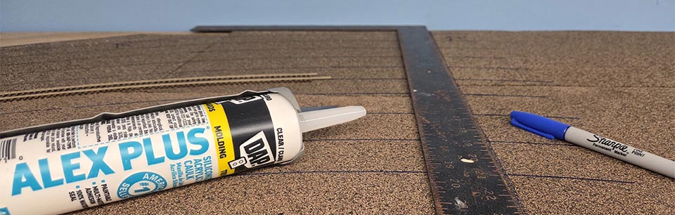
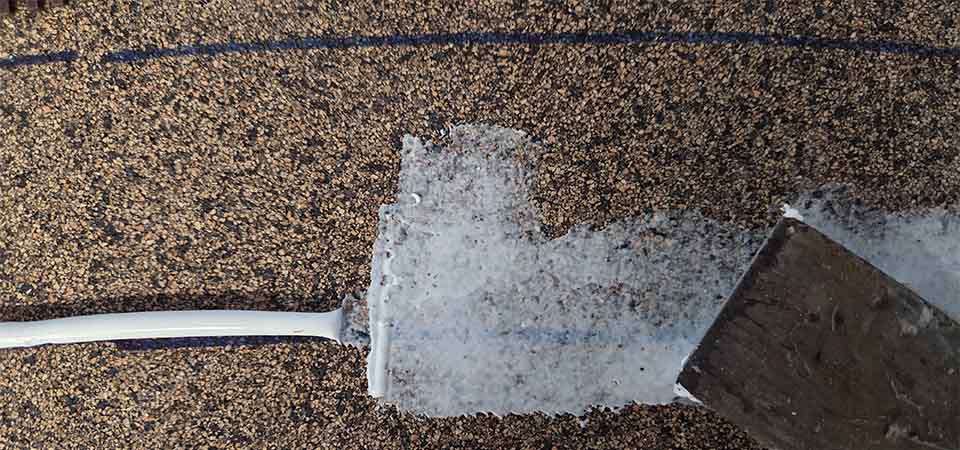
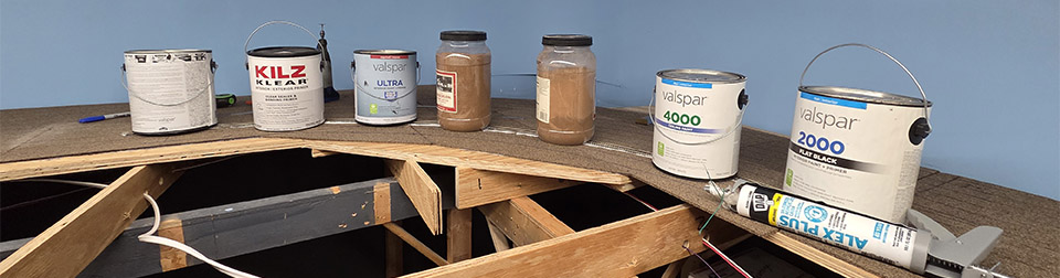
As with the rest of the layout, DAP Clear Paintable Silicone Caulking was used to hold down the track. A mark was made at each end of track, a bead of caulking run, then smoothed with a putty knife. The gauge was run down one more time pressing the track into the thin caulk. The center line is always visible which makes this first track very accurate. All other tracks will be spaced off it. Track is weighted down until caulk sets.
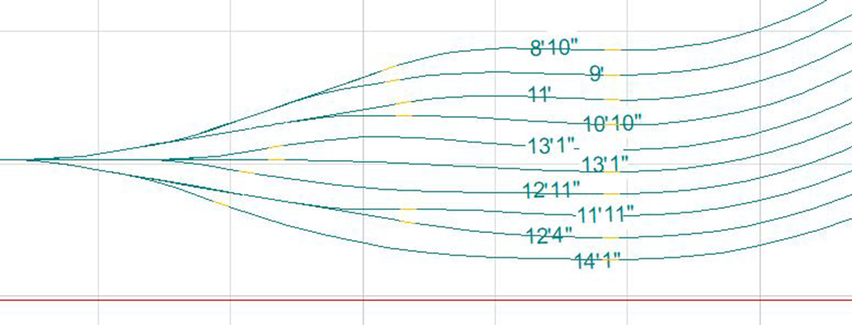
Attached is a drawing of one end of the staging yard. The other end is the same. The numbers indicate the track length from the adjacent track fouling points.